Custom solar mounting systems are the preferred choice for many commercial and industrial projects, ground-mounted power plants, and special rooftop projects. However, customization is not simply a matter of “adjusting dimensions”; it involves multiple dimensions such as structure, materials, installation, and operation and maintenance. From a practical engineering perspective, the following outlines the key aspects that deserve the most attention during the customization process.
I. Define Project Boundary Conditions
The prerequisite for customizing a mounting system is complete and accurate baseline data. This includes:
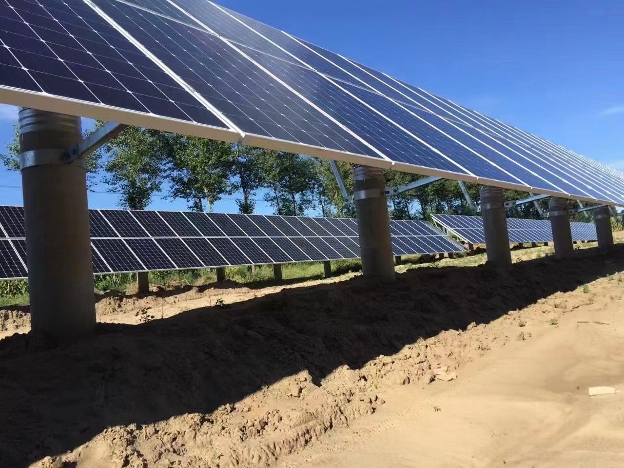
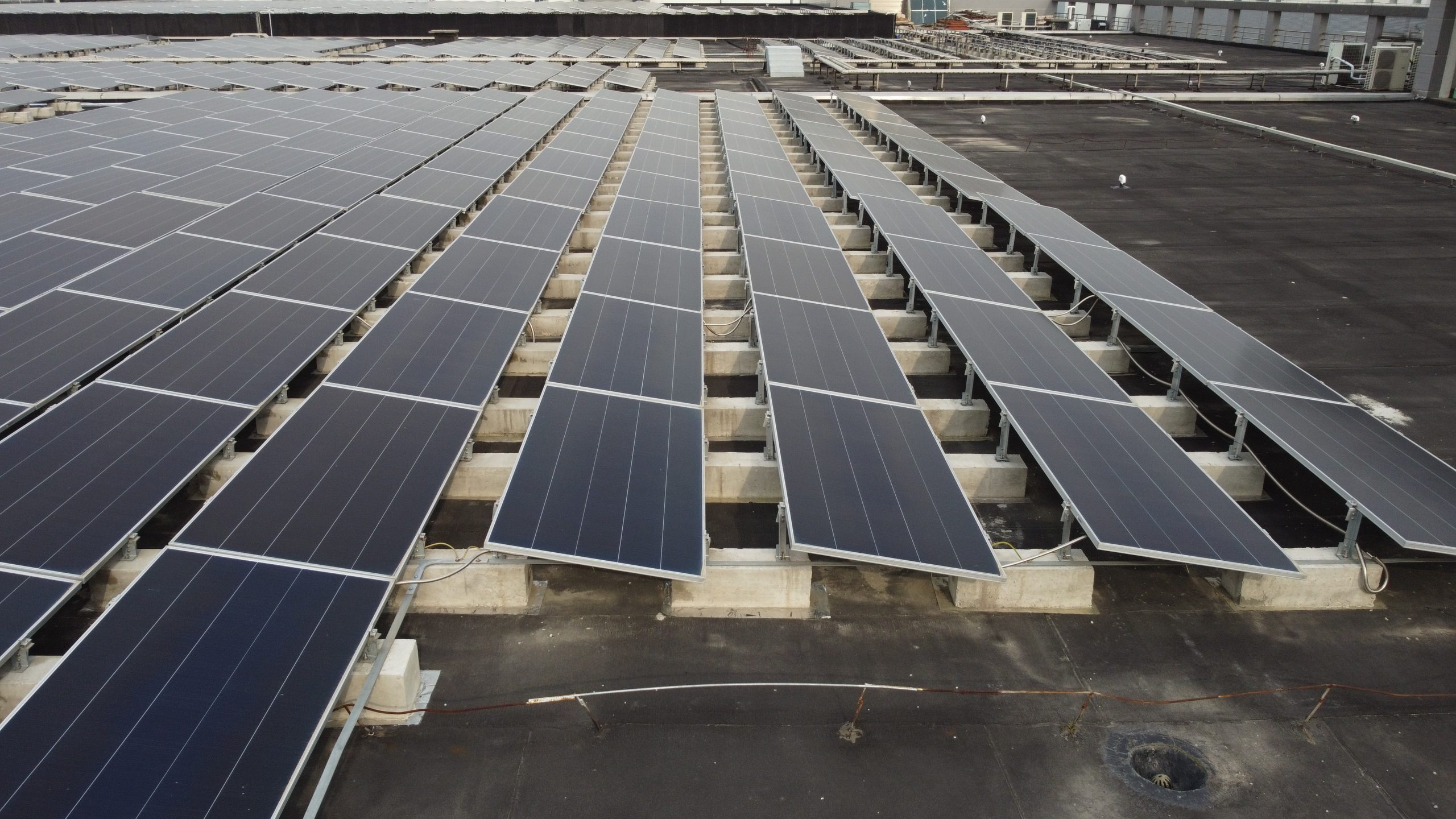
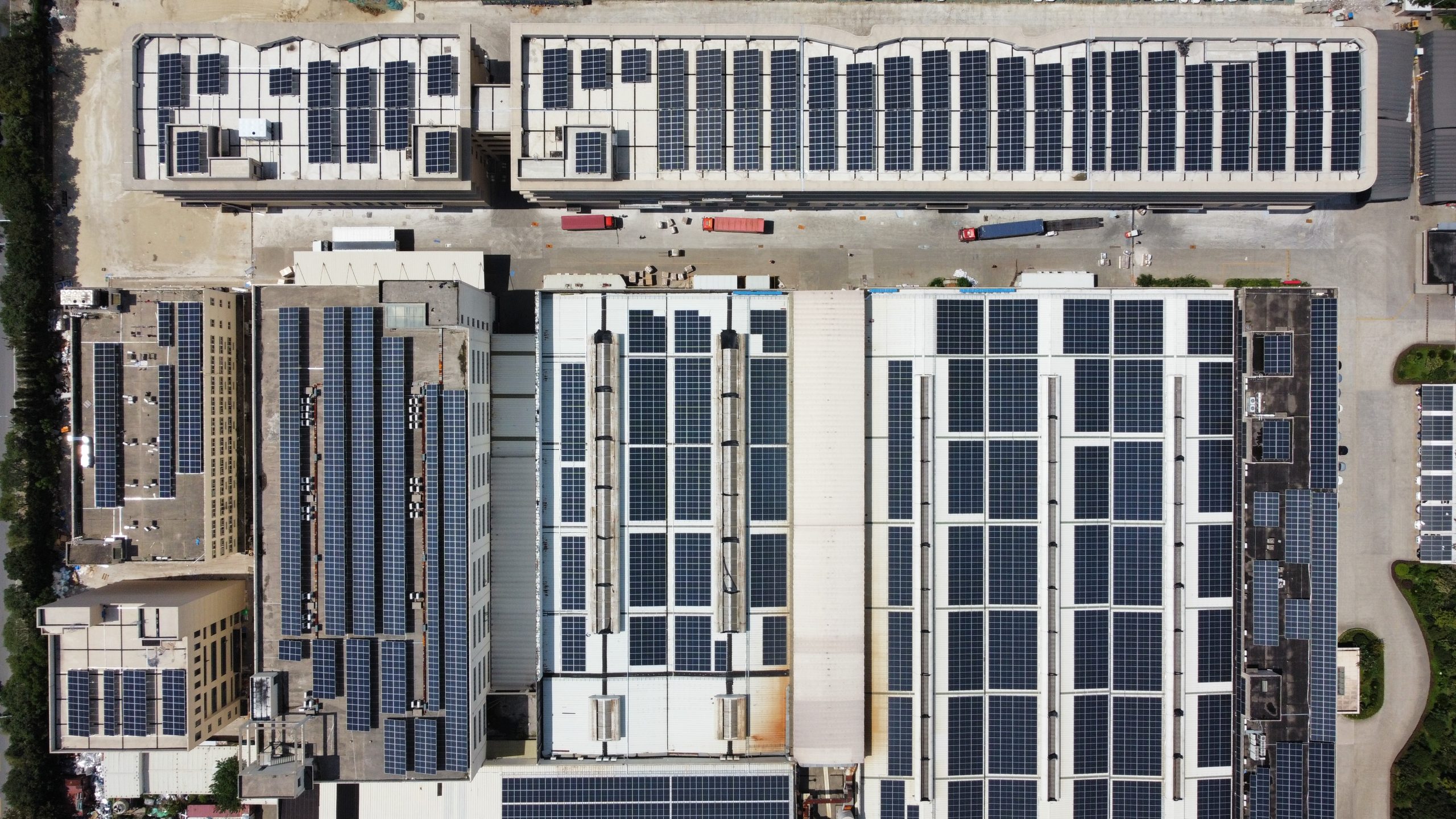
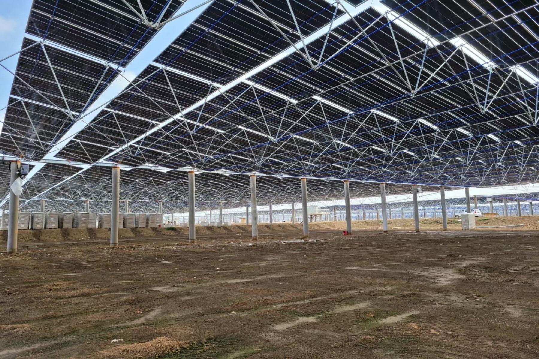
Roof or Site Conditions: Roof type (color-coated steel sheets, concrete, glazed tiles, etc.), load capacity, orientation, slope, and shading conditions; for ground-mounted projects, geological survey reports, topographic maps, and underground utility line distributions are required.
Meteorological and Geographical Information: Basic wind pressure, snow load, seismic intensity, and corrosive environments (e.g., coastal areas or locations near chemical plants).
Module and Electrical Parameters: Module dimensions, weight, junction box locations, and mounting hole spacing; layout requirements for equipment such as inverters and combiner boxes.
These data directly determine the structural form of the mounting system, foundation type, and material selection. The absence of any single item may lead to design deviations, resulting in safety hazards or installation difficulties later on.
II. Structural Safety Is the Primary Principle
Custom mounting systems often employ non-standard structures due to on-site constraints; in such cases, safety margins should not be set too low.
Load Calculations: Calculations must be based on the local 50-year return period for basic wind and snow loads, while also accounting for construction and maintenance loads. For solar arrays, the shape coefficient for wind loads should be determined by zone based on actual tilt angles and locations (e.g., roof edges, corners), rather than being uniformly simplified.
Clear Load Paths: The load transfer path from modules, purlins, columns, and braces to the foundation must be continuous and well-defined. Avoid issues such as excessively long cantilevers, insufficient joint stiffness, and weak fasteners.
Joint Design: Bolted connections, welded joints, and clamps are high-failure-risk areas. Custom components often involve non-standard connections; ensure that the load-bearing capacity of the joints is no less than that of the structural members themselves, and incorporate anti-loosening and anti-corrosion measures.
III. Materials and Corrosion Protection Must Match the Operating Environment
Material selection directly impacts service life and long-term maintenance costs.
Hot-dip galvanized steel: Offers high cost-effectiveness and is suitable for most environments. The galvanized coating thickness must meet the corrosion classification of the project location; for coastal or industrial areas, a thickness of no less than 80 μm is recommended.
Aluminum alloy: Lightweight and corrosion-resistant, suitable for load-sensitive applications such as rooftops. However, attention must be paid to electrochemical corrosion when in contact with dissimilar metals; electrical insulation should be provided.
Stainless Steel: Primarily used for fasteners and highly corrosive environments; it is costly and should not be overused throughout the entire system.
Vulnerable Areas for Corrosion: Cut edges, welded joints, and drilled holes must be treated with corrosion protection. Custom brackets often involve extensive on-site cutting and welding; if not properly treated, these areas can become starting points for rust.
IV. Installation Feasibility Must Not Be Overlooked
A custom design that appears “feasible” on paper does not guarantee efficient and accurate implementation on-site.
Construction Tolerance: On-site foundations or embedded components often have deviations. Custom brackets should incorporate adjustment allowances (e.g., oblong holes, adjustable connectors) to prevent extensive rework caused by deviations of just a few millimeters.
Installation Sequence and Work Surfaces: Complex custom systems may require specific installation sequences, which must be communicated to the contractor in advance. For work at heights or in confined spaces, components should not be excessively heavy, and connection methods should be as simple as possible.
Tools and Techniques: Avoid using specialized tools or techniques where on-site quality control is difficult to ensure (e.g., complex welding, high-torque fastening at heights). The more complex the customization, the greater the difficulty in on-site management.
V. Advance Planning for Post-Construction Operation and Maintenance
Solar power plants have an operational lifespan of over 20 years, yet the ease of maintenance for custom mounting systems is often overlooked.
Maintenance Access: For large arrays or high-density installations, maintenance access paths should be reserved to facilitate module replacement and cable inspection.
Replaceability: Critical fasteners and wear-prone components should be standardized as much as possible to avoid proprietary non-standard parts, which would make replacement difficult years later.
Drainage and Dust Accumulation: Custom structures may alter existing drainage paths; measures must be taken to prevent water pooling and dust accumulation, which can accelerate corrosion or cause hot spots.
VI. Balancing Cost and Delivery Timelines
Customization implies non-stock products, requiring redesign, tooling, or special procurement.
Mold and Processing Costs: Certain irregular cross-sections or specialized connectors may incur one-time mold costs; the cost-effectiveness of these should be evaluated.
Material Utilization: During custom fabrication, the cutting dimensions of profiles and layout methods affect material waste; these should be optimized during the design phase.
Delivery Time Risks: The cycle from detailed design, raw material procurement, and processing to transportation is typically longer than for standard products. When project schedules are tight, key milestones must be planned in advance.
VII. Compliance and Acceptance
Custom-made mounting structures must also comply with national and industry standards, such as the Code for Structural Design of Solar Mounting Structures (NB/T 10115) and the Code for Design of Steel Structures (GB 50017).
Design Documentation: Calculation reports, construction drawings, and detailed node drawings must be provided and reviewed by a qualified entity.
Material Certification: Quality certification documents must be provided for steel, fasteners, galvanized coatings, and other materials to facilitate traceability during acceptance.
Acceptance of Concealed Work: Concealed components such as foundations, anchor bolts, and embedded parts must be inspected and accepted before being covered, and visual records must be retained.
The core principle of customizing solar mounting systems is “adapting to local conditions.” Every customization decision should be based on a comprehensive assessment of site conditions, structural safety, construction feasibility, and long-term operation and maintenance. Overemphasizing initial cost savings at the expense of safety or convenience often results in higher costs later on. A pragmatic and rigorous customization process is the foundation for ensuring the full lifecycle value of a solar power plant.